Skip to content
Frank "Papa" Hermes
…my escapades
Menu and widgets
Previous Image
Next Image
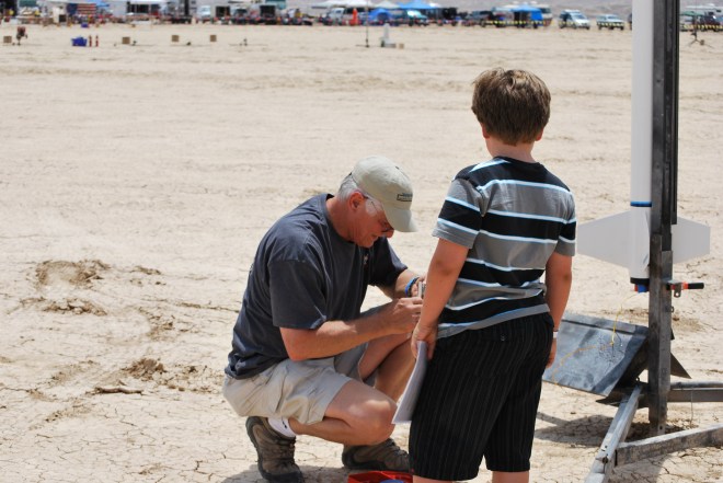
Hermes 3 Launch 008
Leave a comment
Cancel reply
Δ
Post navigation
Published in
Hermes 3 Launch 008
Comment
Frank "Papa" Hermes
Sign up
Log in
Copy shortlink
Report this content
Manage subscriptions